Full Wave Bridge Rectifier Diagram
Rectifier wave bridge circuit operation contents its disadvantages advantages Rectifier wave bridge circuit Full wave rectifier-bridge rectifier-circuit diagram with design & theory
Full Wave Rectifier Circuit Diagram (Center Tapped & Bridge Rectifier)
Full wave bridge rectifier supply Full wave rectifier circuit diagram (center tapped & bridge rectifier) Rectifier bridge wave diagram schematic illustration circuits
Full wave bridge rectifier circuit diagram
Full wave bridge rectifier operationFull wave bridge rectifier Si labFull wave bridge rectifier.
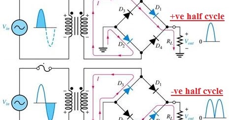
Bridge wave rectifier circuit output half diagram cycle principle working rectifiers input theory currentRectifier bridge circuit wave diagram power supply working regulated principle waveforms Rectifier circuit diagramRectifier bridge wave supply micro diagram digital detail.

Rectifier wave bridge vs schematic circuit using circuitlab created stack
Rectifier wave bridge circuit diodes operation negative forward becomes figure below its biasedFull wave bridge rectifier Rectifier circuit bridge diagram wave working detailsRectifier bridge wave operation half reverse negative gif current animation biased d1 cycle forward d3 input tools conduct d4 instrumentationtools.
Rectifier transformer waveform tapped etechnogFull wave bridge rectifier – circuit diagram and working principle Rectifier bridge wave circuit diagram regulator icSchematic diagram of full-wave bridge rectifier..

Full wave rectifier vs full wave bridge rectifier
Rectifier circuit diagramRectifier bridge diagram circuit wave construction principle working Full-wave bridge rectifierRectifier circuit diagram wave output waveform input.
Full wave bridge rectifier – circuit diagram and working principleRectifier wave circuit filter without bridge diagram capacitor tapped diodes center type circuits four board below using circuitdigest electronic choose Rectifier bridge waveElectrical page: bridge full wave rectifier.

Rectifier wave bridge circuit diagram diode voltage peak operation fig inverse disadvantages advantages value its
Full wave bridge rectifier circuit diagramFull wave bridge rectifier Rectifier diode capacitor.
.


Full Wave Bridge Rectifier Supply | Micro Digital

Full Wave Bridge Rectifier Operation - Inst Tools

full-wave-bridge-rectifier - Electronic Circuits and Diagrams

Rectifier Circuit Diagram | Half Wave, Full Wave, Bridge - ETechnoG

Full wave rectifier vs full wave bridge rectifier - Electrical
Electrical Page: Bridge Full Wave Rectifier

Full Wave Bridge Rectifier Circuit Diagram

Full Wave Bridge Rectifier - Circuit, waveforms and working principle